An incremental rotary encoder that is already connected to an electrical machine and analyzed by a frequency inverter must now be read and analyzed by an HBM Genesis HighSpeed series data recorder as well. Due to the unknown input impedance of the inverter and the unknown potential difference, analysis electronics with electrical isolation will be required between the data recorder and the incremental rotary encoder.
This report describes a circuit for optical separation of the encoder signal, with an introduction to parameterization of Perception software for position analysis. The tracks of incremental rotary encoder HOG75 are recorded with the HBM GEN3i data recorder and the Perception software. The result is then used to determine the current angle of rotation of the motor. This encoder has a resolution of 1024 increments per revolution. The three tracks of the encoder are tapped in parallel to the input of the frequency inverter and read on the GEN2i or the successor model GEN3i via the Digital Event/Timer/Counter connector.
First adjust the resolution under Settings ➔ General ➔ Recorder. 16 bits is selected by de-fault. This needs to be changed to 18 bits to analyze the angle of rotation so that the Timer-Counter Channels can be activated later. 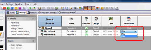
Figure 1: Changing the recorder setting to 18 bits The optical signal converter between the incremental rotary encoder and the GEN3i (see Annex A) is hardwired to the Marker Channels (Events)
Ev A7_01 (encoder track K0)
Ev A7_02 (encoder track K1)
Ev A7_03 (encoder track K2) on input card A. (See the GEN3i data sheet page 8, Figure 1.6: Pin diagram for Digital Event/Timer/Counter connector)
These channels will now be activated in Perception (Settings ➔ General ➔ Marker Channel (Events)):
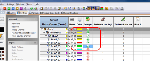
Figure 2: Activating the digital inputs Now activate the appropriate Timer-Counter Channel (Ch A9) under the General menu item to analyze the position:
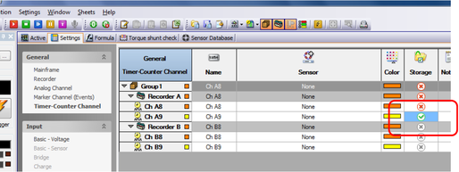
Figure 3: Activating the Timer-Counter Channel
If it has not been done already, create a suitable sensor in the sensor database (Sensor Database worksheet). Initially no direction will be analyzed (select Counter Type: Uni Directional). To reset the counter after 1024 pulses, select option Reset counter each external pulse. Make the other settings shown in the figure below as well:

Figure 4: Creating an incremental rotary encoder in the sensor database
Then you can select the sensor for Timer-Counter input CH A9 under Settings ➔ Input ➔ Timer Counter. The corresponding settings appear on the right:
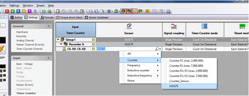
Figure 5: Selecting the sensor you created
Reset the Invert reset pin option:
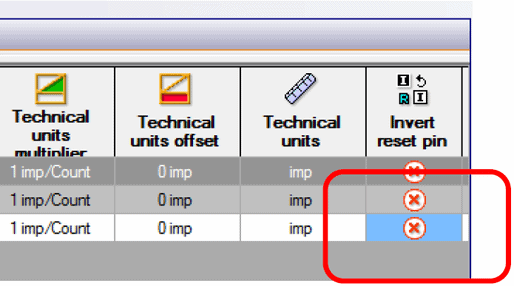
Figure 6: Resetting inversion of the signal
Now you can drag the counter into the Active page and use it as you normally do:
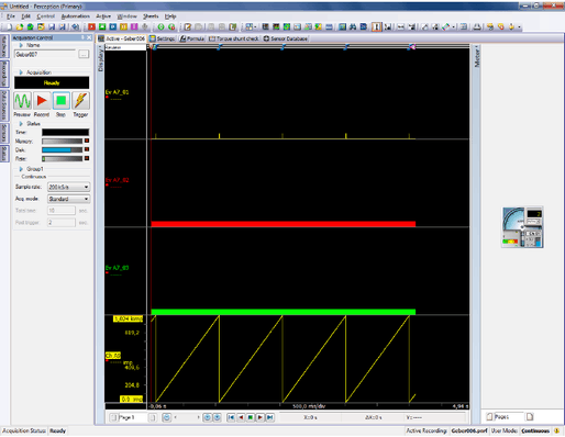
Figure 7: Display of the encoder signal in Perception
The signal converter is used to tap three tracks K0, K1 and K2 of the HOG75 incremental rotary encoder in parallel to the frequency inverter so they can be analyzed on the HBM GEN2i / 3i. The optical coupler is used to separate the potential between the encoder and Genesis. The two LEDs on the top of the unit indicate the status of the two connected devices (encoder and HBM Genesis).

The 44-pin D-Sub connector of the level converter is connected with the digital interface on the top of the HBM GEN3i. The banana plugs are connected to the incremental rotary encoder according to their assignment, in parallel to the inverter.

Figure 8 shows the basic layout of the converter:

Figure 8: Basic layout of the converter

This will bring together HBM, Brüel & Kjær, nCode, ReliaSoft, and Discom brands, helping you innovate faster for a cleaner, healthier, and more productive world.
This will bring together HBM, Brüel & Kjær, nCode, ReliaSoft, and Discom brands, helping you innovate faster for a cleaner, healthier, and more productive world.
This will bring together HBM, Brüel & Kjær, nCode, ReliaSoft, and Discom brands, helping you innovate faster for a cleaner, healthier, and more productive world.
This will bring together HBM, Brüel & Kjær, nCode, ReliaSoft, and Discom brands, helping you innovate faster for a cleaner, healthier, and more productive world.
This will bring together HBM, Brüel & Kjær, nCode, ReliaSoft, and Discom brands, helping you innovate faster for a cleaner, healthier, and more productive world.
This will bring together HBM, Brüel & Kjær, nCode, ReliaSoft, MicroStrain and Discom brands, helping you innovate faster for a cleaner, healthier, and more productive world.
