There are a lot of cables available in the market which may be used for strain gauge applications.
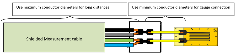
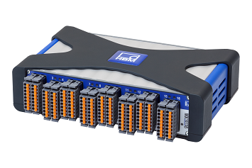
The success of a measurement depends on the right connection cables. Not only do they have to transfer the measurement signals from the sensor to the DAQ system, but they also have to avoid interference signals and resist stress during their use.
Ideally, the cable should not have influence on the strain measurement. In reality, however, cables/wires could have an influence on the measurement signal. The effects of the wires can be minimized to an acceptable level. HBK offers a wide choice of different measurement cables and small-scaled stranded wires for a wide range of applications. There are some important points to consider when selecting the right cable for your application:
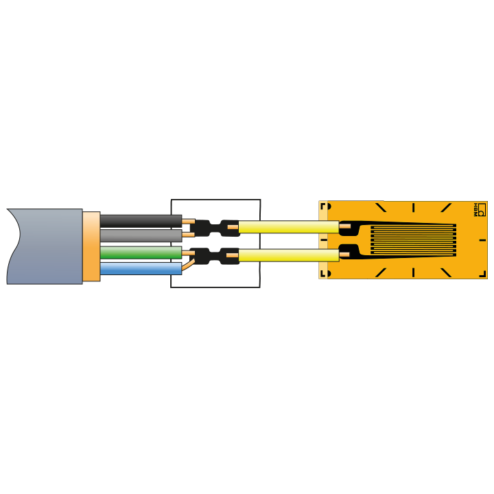
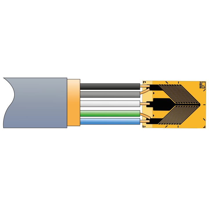
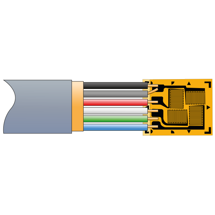
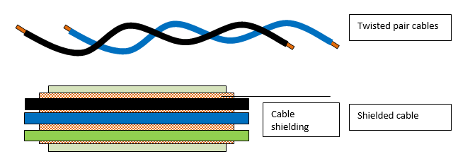
Multi-stranded wires with tin coatings are mostly used for strain gauge applications. Usually, copper conductors are used as wires (most common standard because of good price-to-conduction ratio).
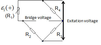
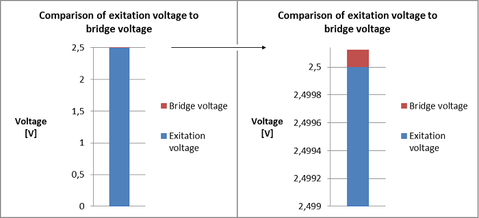
The strain measurement signal in a quarter-bridge configuration is very sensitive:
(0.000125V for 100µm/m strain respectively 0.0025V for 2000µm/m strain). This is visualized in the graphs below for a typical quarter-bridge application.
This measurement voltage signal must not be interfered with by external signals. This is the reason why the right measurement cable is absolutely necessary!
Bridge voltage output signal with 100µm/m strain signal. The bridge excitation voltage (red) is very small in comparison to the excitation voltage (blue)
The quality of a measuring point is not only dependent on the strain gauge itself but also on the type of application and its implementation.
A perfectly functioning measuring point requires a thorough preparation of the application surface, careful bonding, correct connection, and a protective coating.
Connection between the sensor and the amplifier
The coating and the wire insulation influence the temperature range to which they can be exposed. The following diagram shows the typical temperature range of cables depending on their coating.
There are many more requirements on cables such as resistance against different fluids and flammability. The following table provides an overview of typical cable jackets/insulation materials and their temperature range:
Only the 4-wire circuit, or HBK's patented Kreuzer circuit, enables different cable resistances to be compensated for. A known electric current flows through the resistor via two of the leads. The voltage drop at resistor RKab1 is corrected (at high impedance) via two additional leads.
The Kreuzer circuit measures the voltage across resistor RKab2 and adds it to the excitation. The voltage and thus the current through completion resistor Rerg are independent of the cable resistance. Zero point and sensitivity errors resulting from cable effects are electronically compensated for.
1-wire: Connections between strain gauges and solder terminals.
3-/4-wire: For quarter-bridge applications (only 4-wire shown) or full bridges:
5-wire: Half-bridge applications.
6-wire: Full-bridge applications.
Disadvantage: Interference (caused by electric or magnetic fields as well as thermoelectric and galvanic voltages in the measuring circuit) is fully amplified.
Disadvantage: Limited bandwidth