A specially developed deflection sensor seems to be suitable for use in rotor blades and long, extended structures. This sensor is designed to be totally impervious to lightning strikes which, even if they do not actually damage the structure, usually destroy the sensor technology mounted in the rotor blade.
The sensor, which can either be installed during blade manufacture or subsequently mounted into the blade, uses the principle of operation shown in:
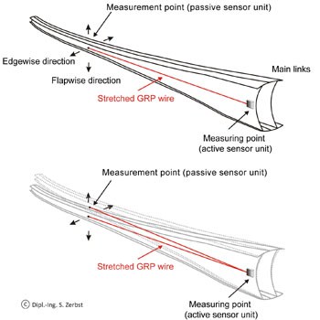
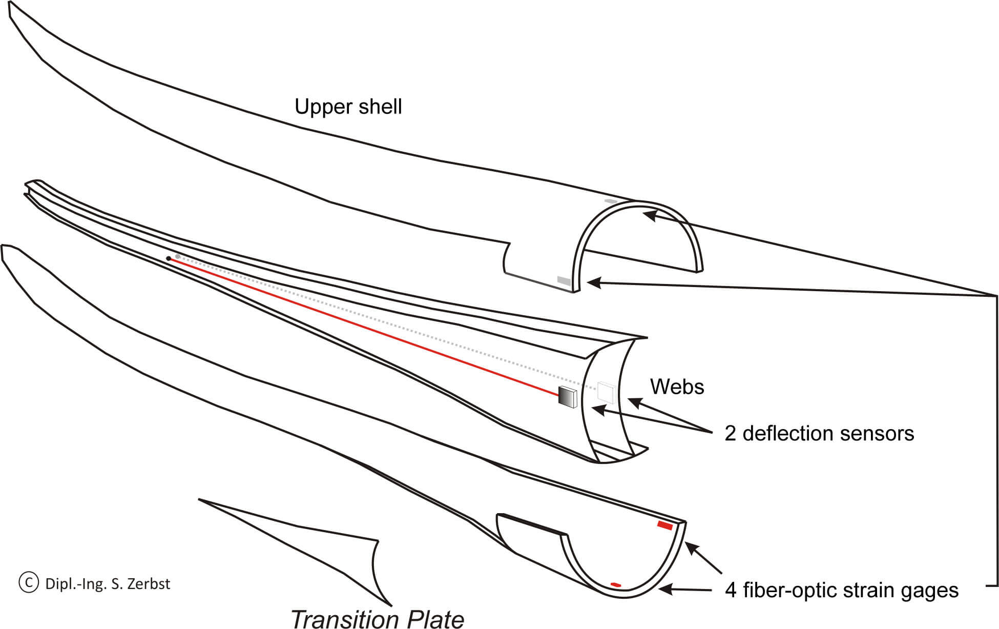
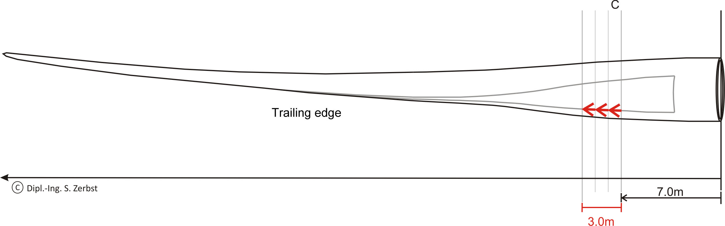
Fig. 1: A special, glass-fiber reinforced plastic (GRP) wire is stretched between the two fastening points. One fastening point resides inside the blade and forms the actual “measurement point” (passive sensor unit). The other fastening point is located at the root of the blade and forms the “measuring point”, the active sensor unit. Fig. 1 shows that the main link of the blade is ideal for deflection sensor installation. The movement amplitude of the blade in the “measurement point” area changes the angle of the GRP wire at the active sensor unit. This change in angle is converted to a deflection signal by two force transducers in an orthogonal arrangement [1]. The system is outlined in
Fig. 2. The sensitivity of the sensor is defined by the tension of the wire, which is kept constant with the aid of a mechanical spring. GRP patches are laminated to the link, and the sensor is attached to these both at the passive and active ends, as shown in Figs. 3 and 4.
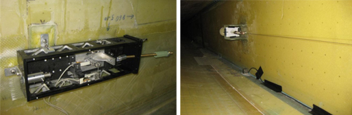
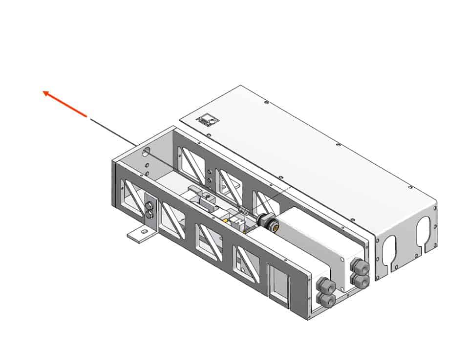
| Fig. 3 Active sensor unit of the deflection sensor |
| Fig. 4 Fastening point in the blade (measurement point) |
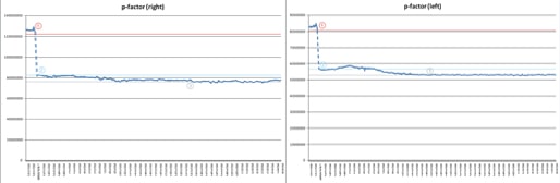
The active unit is so tightly sealed in the rotor hub area, that it is given adequate lightning protection. All the sensor components further on in the blade are non-metallic and therefore not at risk. If the distance between the active and the passive sensor unit is 20 m and the tension of the wire is a constant 300 N, the following are the relevant characteristic values for the deflection
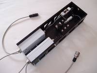
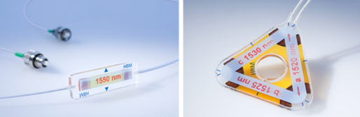
Fig. 5 HBM deflection sensor with measurement electronics installed |
- Non-linearity: < 0.1%
- Temperature coefficient of transducer
- zero signal (TK0): < 3*10-5/K
- Temperature coefficient of transducer
- sensitivity (TKC): < 3*10-5/K
- Sensitivity: 20 μm at 20 m sensor length
- Measuring range: ±200 mm
- Resolution: 1:104.
The transducer evaluation electronics also satisfy demands for ultra-long-term stability, and have a corresponding level of protection with regard to EMC immunity. As can be seen in Fig. 3, these components are mounted directly in the deflection sensor. Signal coupling between the digital transducer electronics and the radio data communication system uses a digital interface, and complies with the latest standards.