arrow_back_ios

Main Menu

See All Acoustic End-of-Line Test Systems See All DAQ and instruments See All Electroacoustics See All Software See All Transducers See All Vibration Testing Equipment See All Academy See All Resource Center See All Applications See All Industries See All Insights See All Services See All Support See All Our Business See All Our History See All Our Sustainability Commitment See All Global Presence
arrow_back_ios

Main Menu

See All Actuators See All Combustion Engines See All Durability See All eDrive See All Production Testing Sensors See All Transmission & Gearboxes See All Turbo Charger See All Industrial electronics See All S&V Signal conditioner See All DAQ Systems See All Power Analyser See All S&V Hand-held devices See All High Precision and Calibration Systems See All Test Solutions See All nCode - Durability and Fatigue Analysis See All ReliaSoft - Reliability Analysis and Management See All Test Data Management See All DAQ Software See All Drivers & API See All Utility See All Vibration Control See All Acoustic See All Current / voltage See All Displacement See All Load Cells See All Pressure See All Strain Gauges See All Vibration See All Torque See All LDS Shaker Systems See All Vibration Controllers See All Power Amplifiers See All Accessories for Vibration Testing Equipment See All Training Courses See All Acoustics See All Asset & Process Monitoring See All Custom Sensors See All Data Acquisition & Analysis See All Durability & Fatigue See All Electric Power Testing See All NVH See All Reliability See All Smart Sensors See All Vibration See All Weighing See All Automotive & Ground Transportation See All Calibration See All Installation, Maintenance & Repair See All Support Brüel & Kjær See All Release Notes See All Compliance See All Our People
arrow_back_ios

Main Menu

See All QuantumX See All LAN-XI See All SomatXR See All MGCplus See All CANHEAD See All Optical Interrogators See All GenHS See All API See All Microphone Cartridges See All Microphone Sets See All Microphone Pre-amplifiers See All Sound Sources See All Acoustic Calibrators See All Special Microphones See All Accessories for acoustic transducers See All Experimental testing See All Transducer Manufacturing (OEM) See All CCLD (IEPE) accelerometers See All Charge Accelerometers See All Rotating See All Non-rotating (calibration) See All Electroacoustics See All Noise Source Identification See All Environmental Noise See All Sound Power and Sound Pressure See All Noise Certification See All Industrial Process Control See All Structural Health Monitoring See All Electrical Devices Testing See All Electrical Systems Testing See All Grid Testing See All High-Voltage Testing See All Vibration Testing with Electrodynamic Shakers See All Structural Dynamics See All Machine Analysis and Diagnostics See All Dynamic Weighing See All Calibration Services for Transducers See All Calibration Services for Handheld Instruments See All Calibration Services for Instruments & DAQ See All On-Site Calibration See All Resources See All Software License Management

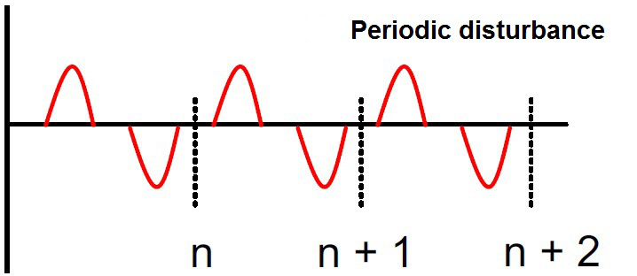
The torque signal in tests of combustion engines exhibits dynamic behavior. The reason for this is vibrations and oscillations caused by the working cycles of each individual cylinder. These dynamic, periodically oscillating torque components are superimposed over the actual torque measurement. The CASMA filter (Crank Angle Sampled Moving Average) works in angular synchronism and is time independent, thus allowing to automatically respond to RPM changes. This filter does not work in the time domain. Instead it works synchronously to the angle. In this article you will learn how to apply the CASMA filter in HBM's TIM-PN, TIM-EC and PMX signal conditioning systems. 

null
null

Filtering the torque signal

Time-synchronous filters

To ensure reliable control, the noisy signal must be filtered or smoothed. Filters such as Bessel or Butterworth work time-synchronously with low-pass characteristics.


Angular filters

The CASMA filter (Crank Angle Sampled Moving Average) works in angular synchronism and is time independent, thus allowing to automatically respond to RPM changes.

How to use the CASMA filter in TIM-PN and TIM-EC

Web Interface

The TIM-EC and TIM-PN torque interface modules offer an integrated web server. In this browser-based software you can use all of the relevant settings for using the CASMA filter.  The required filter parameters are entered via the HTML page and checked for plausibility. The entry point to the CASMA filter is integrated into the "Units and filters" menu.
INTERNAL USE - Case Study  casma casma-filter_english_fig13

Features of the CASMA Filter

Parameterization Characteristic


Parameterization characteristic Function
Angle divider Reduces the angle resolution, thus allowing higher rotational speeds in the same window width
Angle range (degrees) Angle range (window width) over which the moving average operates
Pseudo speed (rpm) After the rpm speed, pseudo pulses or a pseudo speed are generated. Otherwise the filter would stop working and the measured value would freeze.

Information Area Feature


Information area feature Function
Maximum rotational speed (rpm) The angle pulses/s must be less than the sampling rate of the torque measurement. Otherwise the average would be formed via the same measured value.
Pulses per revolution Comes from the number of increments, and the analysis. With active quadrature analysis, the angular resolution is quadrupled
Angular resolution in degrees Calculated from the number of pulses per revolution and the divider
Number of averaged values Computes the number of measured values used to form the moving average

How to use the CASMA filter with PMX

Create a calculated channel

Create a new calculated channel “rotation synchronous filter” in the Analysis category.

Adjust parameters

  • Filter Input: Enter the signal to be filtered here.
  • Shaft Angle Input: Enter the signal of the angle of rotation sensor here. The measured values must be between 0° and 360°.
  • Window Width: Specify the range for taking the moving average. The width must be between 30° and 720°. The default setting is 180°. The ratio of the window width to the resolution must be less than 180.

The window width can be easily determined experimentally by projecting the periodic time on the disturbance to the angle of rotation (see screenshot). In this example, there is a periodic disturbance every 720°.

  • Minimum Speed: This virtual rotational speed is applied when the active rotational speed is less than the defined minimum rotational speed.
  • Resolution: This value determines how often (how many degrees each time) a new average will be calculated. Note that the maximum permitted permissible rotational speed depends on this value because the speed of calculation is determined by the overall update rate.

The theoretical value is derived by: Maximum rotational speed = resolution * overall update rate / 6. For practical purposes you should use values that amount to only 10 to 20% of this theoretically possible maximum rotational speed.

Resolution

The theoretical maximum rotational speed at an overall update rate of 19,200 Hz

The theoretical maximum rotational speed at an overall update rate of 38,400 Hz

3200 rpm

6400 rpm

6400 rpm

12,800 rpm

12,800 rpm

25,600 rpm

19,200 rpm

38,400 rpm

25,600 rpm

51,200 rpm

The following multiples of the rotational speed are suppressed depending on the window width:

Window width

Multiples

90°

4, 8, 12, …

120°

3, 6, 9, …

180°

2, 4, 6, …

360°

1, 2, 3, …

720°

0, 5, 1, 1, 5, …

Note: If one of the source signals is invalid, the output signal will be invalid as well.

CASMA in action

You will see the unfiltered torque signal which is red, and the filter torque signal filtered using CASMA in green.

It can be seen clearly that the CASMA filter achieves excellent stabilization of torque measurements in correlation to the engine speed, which also changes over time. The greater the width of this filter, the better the results.

knowledge, resource center, articles, using the casma filter for torque measurements tips tricks

Example

In this short example, PMX is used for analyzing power P[W], rotational speed n [1/s] and acceleration [1/s²], in addition to torque M [Nm] and the corresponding CASMA filter. The calculated channels as shown in the screenshot below have been created for this purpose. The signals are displayed in catman.

knowledge, resource center, articles, using the casma filter for torque measurements tips tricks

Calculations

Power:

Angular speed:

Angular acceleration:

Important: For all calculations the rotation speed n has to be converted from revolutions per minute to revolutions per second, i.e. divided by 60.

Channels

Please see below for all channels displayed graphically in catman. The colors in brackets refer to the colors of the curves. The signals consist of the following channels:
Torque M (red):

  • Directly from the measurement channel of the PX460

CASMA filter (green):

  • Already explained in detail

Power P (yellow):

  • Divider (rotational speed n / 60), revolutions per second
  • Constant signal (2*pi)
  • Multiplier (M * n [1/s] * 2*pi]

Rotational speed n (orange):

  • Directly from the measurement channel of the PX460

Angular acceleration (blue):

  • Multiplier (2*pi * n [1/s]), results in the angular speed w
  • Differentiator (w)

HBK signal conditioners that support the CASMA filter